
Submersible Turbine vs. Centrifugal Booster: Choose Once
Quick Answer: Choose direct draw when the well sustains peak demand on a steady schedule, and storage with a booster when demand is peaky or you want a surface source option.
Two irrigation operations can sit on the same road, farm the same acreage, grow the same crop, and move water in completely different ways. One has a pump hanging in the well casing feeding the mains directly: open a valve and the water arriving at the sprinkler came out of the ground seconds earlier. The neighboring operation runs its well into a storage tank, and a separate pump on a slab beside that tank is what pressurizes the field.
Both layouts work, and both are correct for the operation that built them. What separates them is a short list of physical conditions that were true at each site on the day the system went in, and those conditions decided the architecture more firmly than anyone's opinion did.
That is worth sitting with, because this decision is made once. Mains get trenched, slabs get poured, wire gets pulled, and the layout stays in the ground for decades while the pumps inside it are repaired and replaced several times over. The choice shapes every service visit for the life of the system.
What the Well Gives, and When the Field Wants It
Every version of this decision starts in the same place: what the well sustains through a full set, measured against what the field pulls at its heaviest moment, and when in the day it pulls it.
One thing has to be settled before either half of that is worth measuring. If a well that used to carry a field no longer does, something has changed at the source, and that change deserves its own diagnosis rather than an architecture built around it. Everything below assumes the well is delivering what it is actually capable of delivering.
Direct draw is the simpler machine. A submersible turbine sits below the water level in the casing and pushes straight into the mains. It is the default for deep-well agricultural irrigation for solid reasons: nothing needs priming, the motor is cooled by water moving past it, and there is no second pump in the chain to fail. Line-shaft turbines are mainly used where an operator wants the motor above ground. Either way, the well is the entire supply, and the mains see exactly what the well produces. If sustained delivery meets or exceeds what the field wants during a peak set, direct draw is not merely adequate; it is the layout with the fewest parts in it.
Depth matters less than delivery here. Agricultural wells into the Floridan Aquifer commonly land anywhere from roughly 100 to 400 feet, and depth mostly tells you what it takes to reach and service the pump, not what the well gives you in the middle of a set.
The second half of the question is the shape of the demand rather than its total. Steady draw means one zone at a time, long sets, roughly the same flow for hours, and direct draw fits that profile cleanly because the well is asked for a rate it can hold rather than one it can only touch briefly. Peaky draw is the opposite: several zones opening together, short, high-flow sets, or a schedule that has to move a large volume within a narrow window due to labor, wind, or the crop's tolerance. Two operations with nearly identical annual water use can land on opposite sides of that line purely because of when they need it.
When Demand Outruns the Well
A storage tank does one thing no length of pipe can: it breaks the direct link between the rate at which the aquifer releases water and the rate at which the field takes it. The well fills the tank at whatever rate it comfortably sustains, running long and low across the day, while the second pump empties it at whatever rate the field wants during the window that matters. Each pump is matched to one job, and neither side compromises for the other.
That is an architectural answer to a demand-shape problem, not a repair for a supply problem. Storage layered over a declining well masks the symptom for a while, then runs out at the least convenient moment.
Storage also opens a door direct draw does not have. A tank is indifferent to where its water came from, so some operations fill from a pond, ditch, or river, or keep a surface source as a backup fill.
A tank fed from a pond, ditch, or river carries whatever the surface carries. Sediment loads the intake screen, and biofilm grows on wetted surfaces, so that intake becomes a scheduled maintenance item, not a part you install and forget.
What Direct Draw Asks of the Equipment
Day to day, direct draw puts the whole job on one motor. Agricultural pumps running four to eight hours a day sit in continuous-duty territory, and the motor has to be built for that rather than for intermittent service.
What direct draw does not give you is anything between the pump and the field. Every zone change, every valve that shuts early, every emitter that plugs is felt at the pump itself, because there is no stored volume in the middle to absorb it. How that pattern of starts and load swings translates into wear is a subject of its own, and it applies to whichever motor is carrying the work rather than deciding between the two layouts.
The other thing direct draw asks is patience about location. The pressure your field runs on is generated at the bottom of a casing. Everything that can go wrong with it is down there too.
What the Storage Layout Asks of the Equipment
The storage layout splits the job across two machines and asks something different of each.
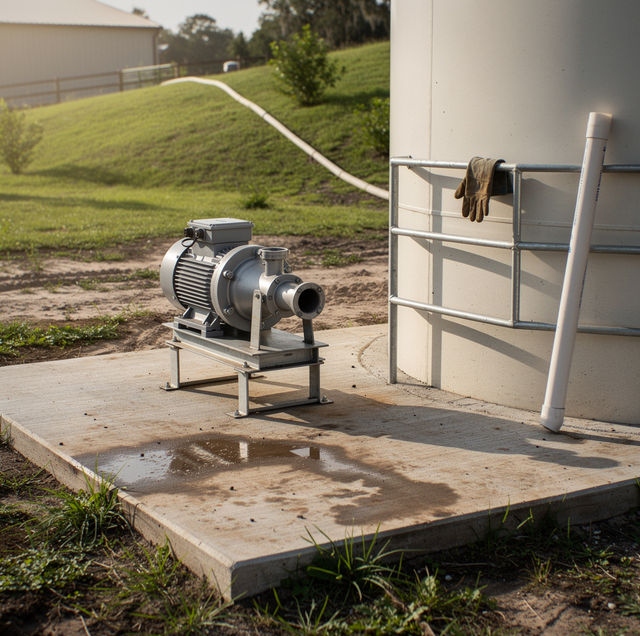
The well pump has the easier life. It fills a tank rather than fighting a pressurized main, and it can run long, low, and undisturbed. The centrifugal booster on the slab has the harder assignment. It sits above ground, exposed to sun, dust, and weather in a way nothing down a casing ever is, and it carries a service and wear profile of its own that is worth understanding separately from this choice.
Priming: a centrifugal booster only moves water once the pump body and the suction line are full and free of air. A submersible never faces this, being already underwater; a surface pump faces it every time it loses its water.
Siting: suction lift is capped by atmospheric pressure, which sets a practical ceiling near 25 feet at sea level, and is considerably lower once you account for friction in a long suction run. In practice, the booster wants to sit low and close to the tank rather than tucked into a convenient corner of the yard. Poor siting at this one point results in a pump that primes fine on installation day but loses prime as conditions shift.
The tank itself: it is not a passive vessel. It has a fill control, a level reference, an outlet, and a way to keep sunlight and debris out, each of which is another item on the inspection list.
Service Access and Downtime When Something Fails
Access is where the two architectures diverge most sharply, and operators feel it every time something needs attention.
Reaching a submersible turbine means a rig at the wellhead, the discharge broken loose, and the drop pipe brought up in sections. The field is down for the duration, and the work depends on weather and access in a way ground-level work does not. Reaching a booster on a slab means unbolting it where it stands. The difference is not subtle.
The trade is that a storage layout has more pieces: two pumps, two sets of controls, and a tank mean more places for a fault to start. What that added complexity gives you is that the parts most likely to need routine attention sit at waist height.
| Interruption | Drawing direct into the mains | Well to storage, second pump to the field |
|---|---|---|
| Power drops mid-set | Mains lose pressure immediately, and the set stops | The set stops, but the stored water is still there when power returns |
| Well pump fault | Whole system down until the pump is pulled | The field runs on what the tank holds, then stops |
| Booster fault | Does not apply | The well can keep filling, but the field has no pressure |
| Sediment carried in from the source | Goes straight into the mains, filters, and emitters | Sediment has somewhere to settle before the second pump picks it up |
Where the Decision Usually Lands
Most sites tip one way before anyone starts comparing equipment. A well that comfortably covers peak demand, on a steady set schedule with no interest in a surface source, points at direct draw and its smaller parts count. A field with peaky demand, or one that wants the option to fill from more than one source, points to storage and accepts a second pump and a tank in exchange.
The sites needing real thought are the ones close to the line, where the well roughly covers peak demand with nothing spare. There, an honest look at future acreage, future crop, and how much interruption the operation can absorb matters more than any single measurement taken on one afternoon.
If the layout is on paper, walk the site before picking equipment. Where the tank can sit, how far the booster would be from it, and how the mains run often narrow the choice on their own.
Frequently Asked Questions
Both have motors that a surge can reach, but not equally. Submersible motors are widely regarded as more surge-vulnerable than surface motors on the same site, and one cannot be inspected without pulling the pump. Surge arrestors are wired ahead of the motor at the control box or panel, so a storage layout gives you two separate points to protect rather than one.
Not always. Submersible booster units are built to mount horizontally in a pipeline rather than in a well, and they run quieter than a surface pump because the motor sits inside the water passage. The trade is access: a surface centrifugal can be looked at, listened to, and unbolted without opening the line, which is why most storage systems still use one.
A low-level cutoff. A float switch or a level probe in the tank is wired into the pump's control circuit so the motor drops out before the water does. Without that, the pump keeps turning with nothing to move, and the first casualty is usually the mechanical seal, which depends on the water passing through to carry heat away from its faces. That failure is quick and often goes unnoticed until the seal starts weeping.
Yes, and it usually traces back to how the tank is filled rather than to a leak. A fill line discharging above the water surface pours air in with the water, and that entrained air travels toward the pump suction. The install-side answers are mechanical: the fill pipe is run below working water level or turned down at the outlet, the suction takeoff is kept clear of the fill point, and air-release fittings go in at system high points. A check valve on the fill line keeps the tank from draining backward when the well pump stops.
It can, and the surprise is usually what happens to the existing well pump. Discharging into an open tank at close to atmospheric pressure is very different work from pushing against a pressurized main, so the pump shifts to a different point on its performance curve, and both flow and motor load change with it. Some units tolerate that fine. Others exceed the motor is rated capacity and require restaging or replacement, along with their controls.
More than people expect. Larger irrigation motors are commonly three-phase, and a field served only by single-phase power either limits motor size or requires a phase converter with a magnetic starter sized to match. That constraint quietly favors whichever layout keeps the largest single motor smallest: splitting the work between a well pump and a booster means two moderate motors instead of one big one. Where the service at the pole is limited, that alone can settle the architecture.
Talk through your irrigation layout before the next pump goes in — get the architecture aligned with what your well and field actually do. Perry-Pump Repair Service LLC serves Lake Butler, Gainesville, and Alachua. Call (352) 320-2412.
